

Product Structure Features
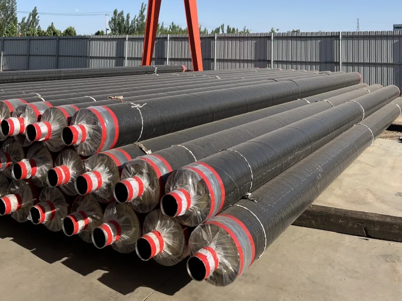
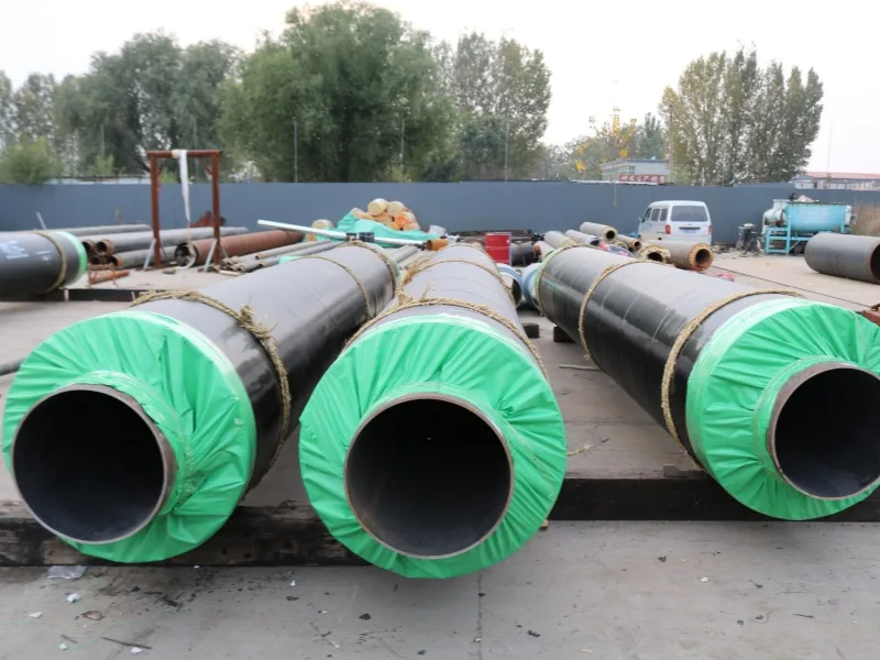
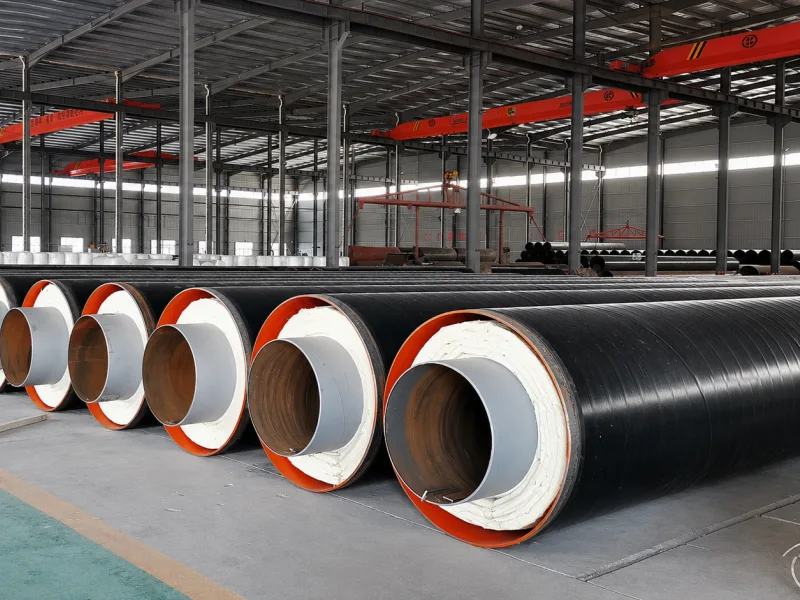
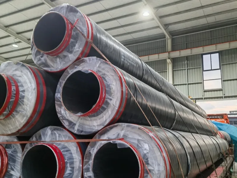
The steel casing steam direct-buried pre-insulated pipe system consists of multiple functional layers, including a steel service pipe, thermal insulation layer, radiation shielding layer, air insulation layer, insulated high-strength sliding (or rolling) supports, and a corrosion-protected outer casing. The structural design is illustrated below.
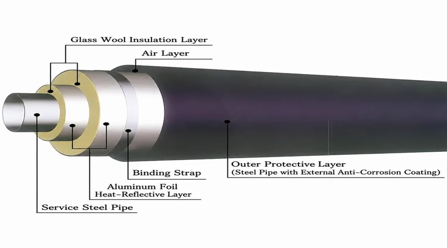
Structural Features of Steel Casing Steam Direct-Buried Pipe
High-Strength Sliding (Rolling) Supports
The service steel pipe is equipped with specially designed, thermally insulated, high-strength sliding or rolling supports that contact the inner wall of the outer steel casing. This design maintains the concentricity of the inner and outer pipes, allows the insulation material to move together with the service pipe, prevents mechanical wear and pulverization of the insulation, and keeps the service pipe deflection within the allowable range.
The insulated high-strength sliding or rolling supports are fitted with high-temperature-resistant pads at least 50 mm thick, effectively preventing thermal bridges between the inner and outer pipes. The specially designed rollers reduce the coefficient of friction to approximately 0.02–0.05, significantly minimizing friction between the inner and outer pipes.
Air Gap Moisture Drainage Design
A 10–20 mm air gap between the insulation layer and outer casing provides additional insulation and creates an effective moisture drainage and monitoring channel.
High-Temperature Insulation System
The insulation layer of the service steel pipe is made of aluminum silicate and centrifugal glass wool composite materials. Depending on customer requirements, other high-temperature insulation materials may also be used, such as ultrafine glass wool, asbestos-free calcium silicate, calcium silicate, or rock wool.
The insulation thickness is determined according to factors such as the operating medium and soil conditions, ensuring that the thermal insulation performance of the directly buried pipeline meets the required standards.
Advanced Anti-Corrosion Protection
The outer steel casing adopts reinforced 3PE or polyurea coating with a breakdown voltage above 5000V, providing over 30 years of corrosion protection.
Internal Fixed Support Technology
The internal support design eliminates the need for traditional anchor blocks, reducing construction costs and improving pipeline reliability.
Fully Sealed Pipeline Structure
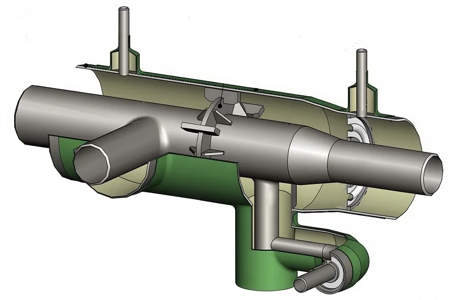
Elbows, tees, and expansion joints are installed inside the steel casing, ensuring safe and reliable operation in a fully sealed environment.
Sealed Drainage System
The condensate drainage system of the directly buried pipeline adopts a fully sealed structure. The drain pipe is connected to the lowest point of the service steel pipe or to the location specified by the design, eliminating the need for a separate inspection chamber.
Butt-Joint Outer Casing Connection
The butt-joint installation method reduces stress concentration and improves the durability of casing connections.
Specification Table of Prefabricated Direct-Buried Steam Insulation Pipe (External Sliding Type)
| Nominal Diameter | Carrier Steel Pipe OD × WT mm | Outer Steel Casing OD × WT mm | Insulation Thickness mm | Weight kg/m | Product Length m |
| DN50 | 57 × 3.5 | 219 × 6 | 60 | 37 | 12 |
| DN65 | 76 × 4 | 273 × 6 | 80 | 55 | 12 |
| DN80 | 89 × 4 | 325 × 6 | 90 | 73 | 12 |
| DN100 | 108 × 4 | 377 × 7 | 100 | 86 | 12 |
| DN125 | 133 × 4.5 | 426 × 8 | 110 | 101 | 12 |
| DN150 | 159 × 5 | 478 × 8 | 120 | 104 | 12 |
| DN200 | 219 × 6 | 529 × 8 | 120 | 166 | 12 |
| DN250 | 273 × 7 | 630 × 8 | 130 | 207 | 12 |
| DN300 | 325 × 8 | 630 × 8 | 130 | 247 | 12 |
| DN350 | 377 × 9 | 720 × 8 | 140 | 293 | 12 |
| DN400 | 426 × 10 | 820 × 10 | 160 | 341 | 12 |
| DN450 | 478 × 10 | 920 × 10 | 180 | 356 | 12 |
| DN500 | 530 × 10 | 1020 × 11 | 220 | 395 | 12 |
| DN600 | 630 × 10 | 1120 × 12 | 220 | 448 | 12 |
| DN700 | 720 × 12 | 1220 × 13 | 220 | 532 | 12 |
| DN800 | 820 × 12 | 1320 × 14 | 220 | 591 | 12 |
| DN900 | 920 × 12 | 1420 × 15 | 220 | 650 | 12 |
Condensate Drainage and Moisture Venting for Steel-in-Steel Pre-insulated Pipes
Optimized Drainage Arrangement
Condensate drainage points are typically installed at intervals of approximately 200 meters and positioned close to fixed supports to prevent damage caused by excessive thermal displacement.
Expansion Joint Integration
When expansion joints are installed, the drainage pipe can be connected through the outer casing of the compensator, ensuring reliable condensate removal during pipeline operation.
Efficient Moisture Removal Design
During transportation and installation, insulation materials may absorb moisture. During operation, heat from the high-temperature medium evaporates the moisture, which is discharged through the air gap and specially designed moisture drainage pipes.
Long-Term Insulation Performance Protection
The moisture drainage system is arranged near fixed supports and can be connected through expansion joint casings, effectively preventing moisture accumulation and maintaining long-term insulation efficiency.
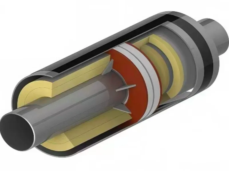
Fixed Support Assembly
Controls axial movement and provides reliable anchoring for steam pipeline systems.
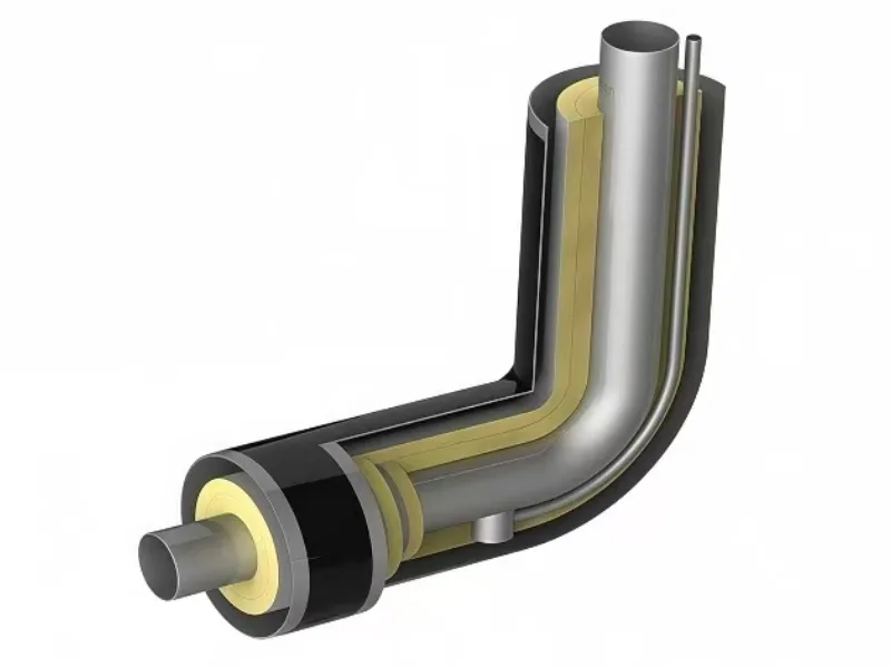
Condensate Drain Elbow
Provides efficient condensate drainage at above-ground transition points.
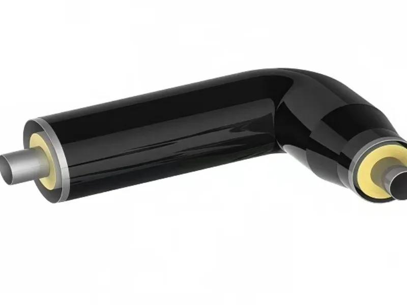
Expansion Compensation Elbow
Designed to absorb thermal expansion and maintain safe pipeline operation.
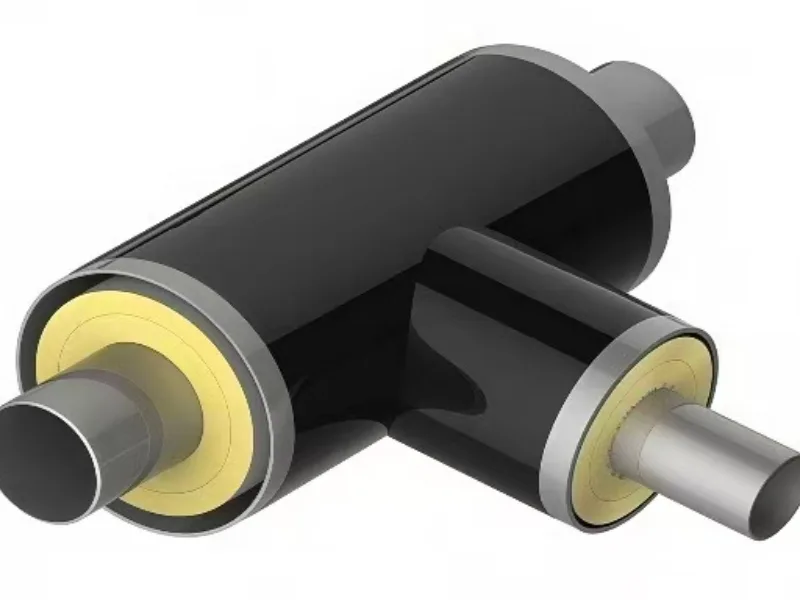
Insulated Steel Casing Tee
Ensures reliable branch connections with continuous insulation protection.
Not Sure Which Product Fits Your Project?
Send us your pipe diameter, operating temperature, insulation thickness, density requirement, support type, and drawings. Our team will help recommend the right insulation product and quotation plan.